53A-220 STRAIN GAGE AMPLIFIER CARD
ORDERING INFORMATION
53A·220 – Strain Gage Amplifier Card
OPT 01 – Auto Null Calibration
OPT 1V – Add VXIbus Compatibility
• 4 channels of 4-, 6-, or 8-wire strain gage inputs
• Separate amplifier for each channel with 9 gain settings plus programmable filters and calibration shunts
• Optional automatic system-tare calibration
• On-card bridge excitation source
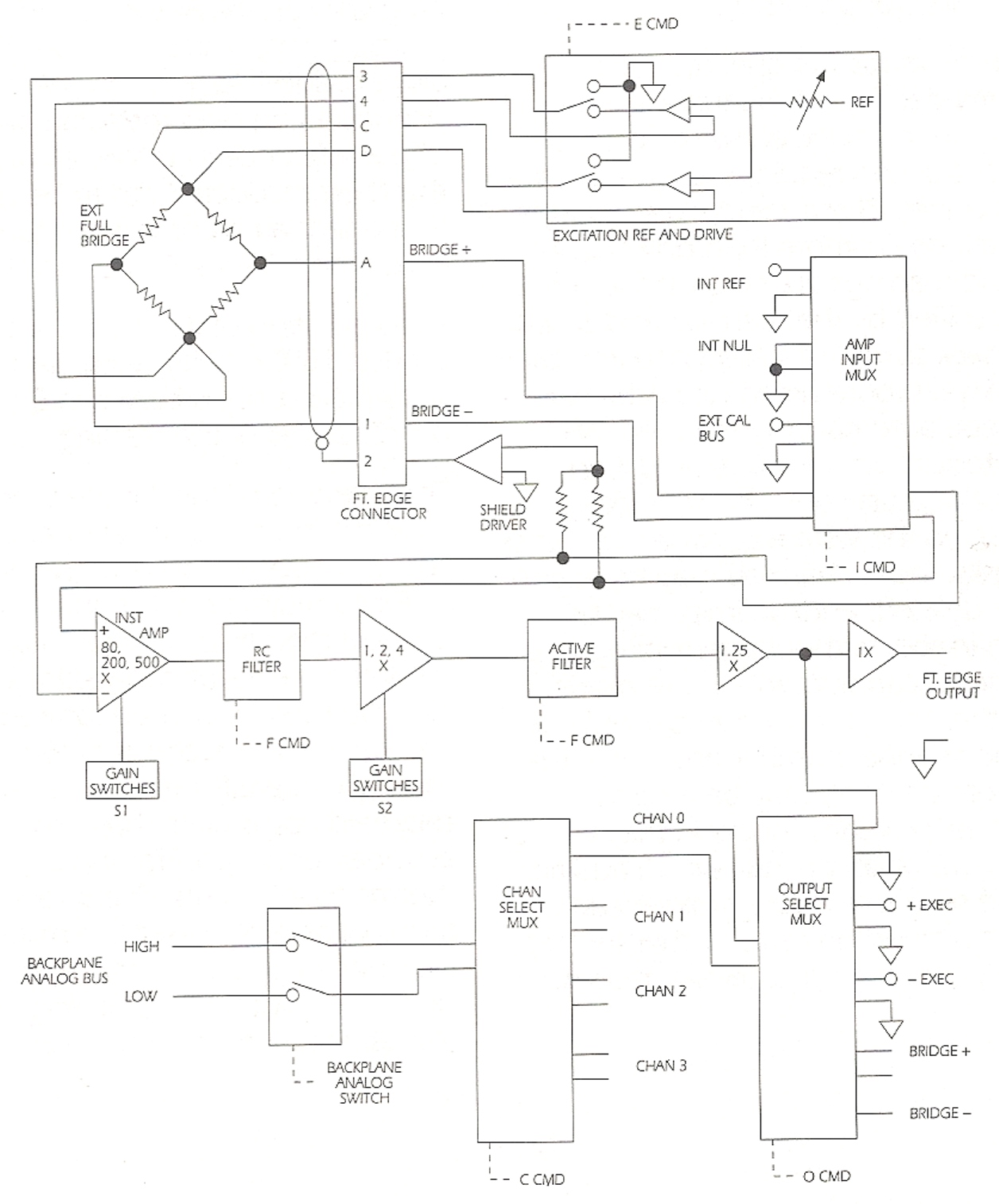
The Strain Gage Card provides four channels of amplification with nine switch-selectable gain settings from 100X to 2500X for each channel. The outputs of each channel may, under program control, be routed to the front edge connector or to the analog backplane bus of the CDSbus™ System. Actual analog measurement is performed by the 53A-522 Digital Multimeter, the 53A-518 Transient Digitizer, the 53A-519B Data Acquisition Subsystem,or by a user supplied DVM
On-card completion for any combination of quarter, half. or full bridge circuits is provided. Each channel has both positive and negative regulated DC bridge excitation voltages with remote sensing capability. Either or both excitation voltages on a given channel may be turned on or off under program control to allow for detection of open bridge arms. Either a 10 Hertz low pass filter or a user-defined filter may be switched in under program control on an individual channel basis.
Shunt calibration under program control is provided for each channel. The user may select between an on-card or an external shunt resistor. In order to facilitate calibration. either the amplifier output or the excitation voltage may be switched under program control to the external multimeter. In addition. the input to each amplifier may be switched between bridge input. external calibration bus input, on-card reference voltage input on-card null input
Option 01 to the Strain Gage Card allows the user to automatically calibrate the strain measurement system by providing a programmable offset adjustment that nulls each channel’s amplifier output prior to applying a load to the strain gauge bridge.
Specifications General
Number of Channels:
Four, any combination of quarter, half, or full bridge circuits.
Bridge Completion:
On-card component solder terminals for completion of quarter and half bridge circuits.
Excitation:
Individual + and – excitations with remote sensing capability. Potentiometer adjustable 0 to 18V dc. differential.
Null Calibration:
Potentiometer: adjustable. Option 01, adjustable under program control.
Amplifier Inputs:
External Bridge Input, external calibration bus, internal short, or internal 10 mV reference.
Amplifier Gains:
Nine Levels. switch-selectable: 100, 200, 250, 400, 500, 620, 1000, 1250, or 2500.
Amplifier Bandwidth Selection:
Program Selectable for Each Channel, one or two low-pass filters following instrumentation amplifier. Shipped
with 3 dB points set to 10 Hz and 1 MHz. Resistor sockets provided for user filter 3 dB point selection.
Outputs to Card Cage Backplane Analog Bus:
For each channel the following signals may be switched under program control onto the card cage analog bus:
+ excitation voltage, – excitation voltage. amplifier output or amplifier input.
Front Edge Connector Outputs:
Buffered amplifier output for each channel. Any of the signals listed under Outputs to Card Cage Backplane Analog Bus may be switched to the Front Edge Connector under program control.
Programmed By:
ASCII Characters.
Recommended Cables:
53A-748.
53A-780.
Available Options:
OPT 01, auto null calibration.
OPT 1V add VXIbus compatibility.
Amplifier Characteristics (each channel)
Output Range:
± 10V de
Output Drive:
±4 mA.
Accuracy/Bandwidth (6 months, 25°C ± 5°C):

Gain Drift:
100 ppm/°C.
Non-linearity:
0.05%.
Input Characteristics (each channel)
Type Input: Two-wire differential with driven shield.

Input Impedance:
>500 KOhms.
Common Mode Range:
±10V dc.
Common Mode Rejection:
DC – 60 Hz, >90 dB.
60 – 100 KHz, >50 dB.
Over Voltage Protection:
±55V peak to peak.
External Calibration Bus Range:
See Input Range Specification.
Calibration Bus to Input Terminal Tracking:
Null, 2 µV RTI.
Gain, 0.1%.
Calibration Bus Protection:
± 10V peak to peak
Internal Reference Accuracy:
10 mV, ±0.5%. 1 year.
Internal Reference Drift:
±200 ppm. 1 year:
Excitation Characteristics (each channel)
Drive Capability: 0 to 150 mA.
Output Protection:
±50V dc for up to 15 seconds.
+Excitation, – 2V to +50V dc indefinitely.
-Excitation. +2V to – 50V dc indefinitely.
+ to – Excitation, shorted indefinitely.
Drift with Remote Sense:
50 µV/°C.
Excitation Tracking:
±0.3%.
Adjustment Range:
0 to 18V dc. differential.
Remote Sense Overvoltage Protection:
±50V dc.
Shield Drive Characteristics Drive Capability:
1000 ft. Shielded Cable, at 10V dc.
±3 mA with up to 0.05 µfd cable shield to conductor capacitance.
Output Protection:
±7V dc and short circuit.