53A-355 Relay Switching Card
ORDERING INFORMATION
53A-365 – Matrix Relay Card
OPT 1V- Add VXIbus Compatibility
53A-719P – Analog Cable
53A-770 – Matrix Switch Expansion Cable (for two cards)
53A-771 – Matrix Switch Expansion Cable (for up to five cards)
53A-772 – Matrix Switch Expansion cable (for up to ten cards)
53A-783P – Hooded Connector
53A-784P – 9 Pin Ribbon Cable Connector
• May be used for both two-wire and four-wire applications
• Can be split into two matrices for greater flexibility
• Expandable in X or Y
• Up to 320 cross-points in single 10 1/2″ chassis
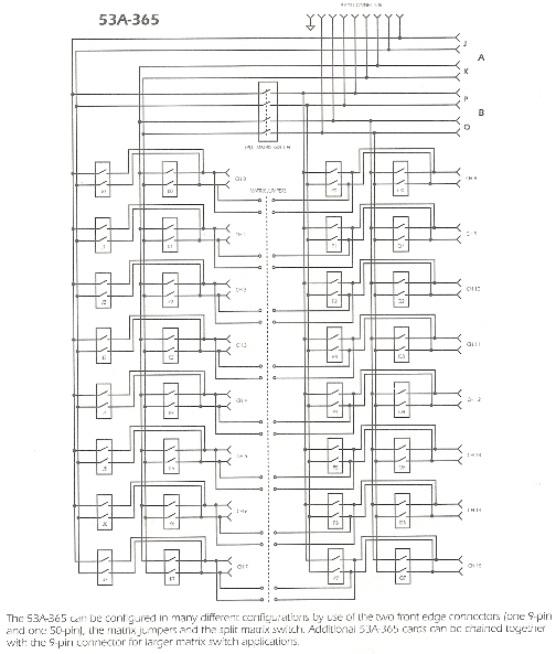
The 53A-365 Matrix Relay Card provides 32 independently controlled DPDT relays which may be configured as either a two-wire or a four-wire matrix in various combinations. Individual relays are independently opened or closed by transmitting ASCII characters from the system controller to the 53A-365.
The 53A-365 is one of the most flexible matrix cards available for CMI Systems. The matrix is organized as wire pairs, and can be configured as two independent 2 x 8 matrices or one 2 x 16 matrix with the on-board Split Matrix switch. In addition, two jumper pads provide the capability to configure the 53A-365 for many two- and four-wire applications.
A few of the possibilities are:

Front panel connectors provide input and output to the unit under test. The front panel connectors allow chaining multiple 53A-365 Cards together to create large matrices. Since chaining can occur in either the X or the Y direction, up to 320 cross points can be available in a single CDSbus™ chassis.
Two additional switches add to the operational and programming flexibility of the 53A-365. The Delay switch inserts a 10 msec delay between each relay opening or closing. A momentary push-button single step switch will step the LED readout through the sequence of the four relay groups. The single step switch is especially useful during software development and as a trouble-shooting aid.
BITE
Built-In-Test Equipment (“BITE”) is provided by a series of LEDs on the front panel, together with the single step switch, that indicate the operational status of the Card. The first four LEDs represent the four relay groups, while the next eight represent the eight relays that make up the group. Lit LEDs indicate that the corresponding relays are closed.
Specifications
Relays:
32 each DPDT relays in 4-wire matrix.
Contact Ratings:
Maximum Resistive, 2.0 Amperes at 28V dc.
Maximum Resistive, 0.3 Amperes at 115V ac 60-400 Hz.
Maximum Inductive, 200 millihenries, 0.75 Amperes at 28V dc.
Initial Contact Resistive, less than 400 milliohms.
Contact Resistive at End of Full Load Life, less than 400 milliohms.
Sealing:
Hermetic.
Operational Life:
500,000 operation minimum, at maximum rated loads.
Duty Cycle:
Continuous.
Switching Rate (max):
100 relay closures per second, nominal.
Dwell:
Dwell time at maximum switching rate is 4 msec minimum.
Signal Path Specifications:
Single-line Thermal Offset, less than 150 microvolts.
Initial Signal Path Resistance, less than 400 milliohms.
Signal Path Resistance at End of Full Load Life, less than 400 milliohms.
Insulation Resistance, greater than ten gigohms between all insulated parts.
Connectors:
One 50-pin, D connector; female.
One 9-pin matrix bus connector.
Programmed By:
ASCII Characters.
Recommended Cables:
See list above in “ordering Information”
Available Option:
OPT 1V, add VXIbus compatibility