53A-469 ARINC 629 COMMUNICATION CARD
ORDERING INFORMATION
53A-469 – ARINC 629 Communication card
OPT 01 – Add 1 Terminal (2 Total)
OPT 02 – Add 2 Terminals (3 Total)
53A-780 – Hooded Connector
• Transmit/Receive on up to three buses simultaneously
• On-board processor dynamically alters data
• Simulate same P/N LRUs with programmable Channel IDs (CIDs) on a word string basis
• Provides 3l bits of time stamp information for each word string received and transmitted
• Includes Serial Interface Modules (SIMs)
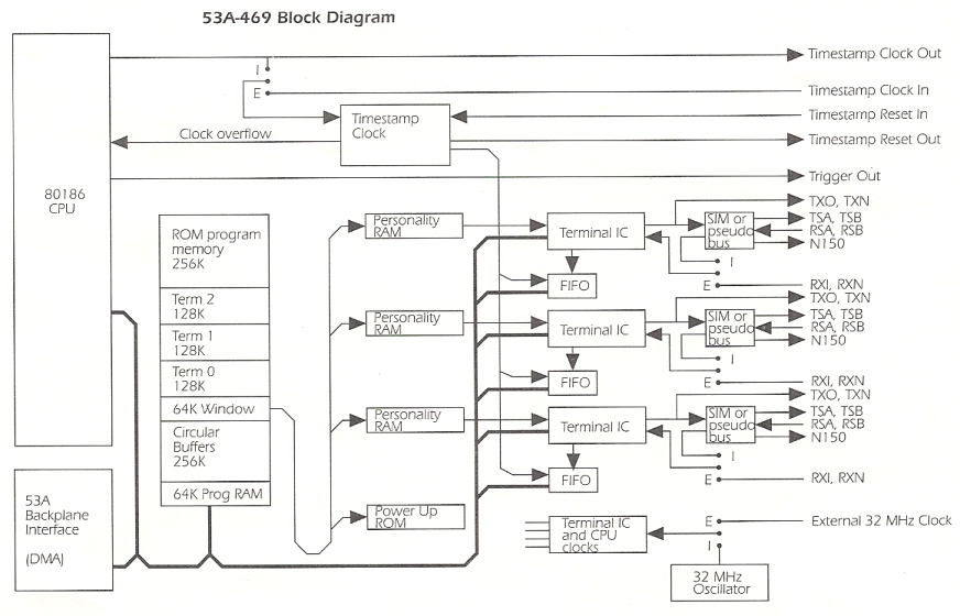
The 53A-469 ARINC 629 Communication Card supports from one to three ARINC 629 terminals. It consists of a main board with one terminal and an optional piggy-back board with one or two additional terminals. The 53A-469 is designed to transmit and receive data on ARINC 629 buses through a current (transformer) coupling device that interfaces to the bus. Data to be transmitted and data that is received is stored in the system memory shared by the terminal IC and an on-board 80186 processor. The transmit schedule and system memory data locations are stored in a Transmit Personality RAM. A Receive Personality RAM and a Multiple Personality RAM contain information on which data to receive and where to store it in the shared system memory.
Each ARINC 629 terminal on the 53A-469 Card consists of:
– system memory;
– a personality RAM;
– a terminal protocol IC which interprets the personality RAM;
– a Serial Interface Module {SIM) that modulates/demodulates the Manchester coding.
Note: To help insure optimum ARINC 629 compatibility, each terminal uses the VLSI Terminal IC and Serial Interface Module (SIM) developed by Boeing.
A pseudo bus module that replaces the SIM and provides a voltage bus without SIMs or current couplers is available.
The 53A-469 allows the user to program the Personality RAMs and to read and write data from/to the system memory. It also allows installation of a user-programmed 64 Kbyte PROM which is read on power-up to program the Personality RAMs and set up transmit data in the system memory for all three terminals.
ARINC 629
ARINC 629 is a bit-serial time multiplexed multiple transmitter data bus developed for use primarily in commercial aircraft. All data transmitted on the ARINC 629 bus consists of at least a label. Zero to 256 16-bit data words follow a label.
Using a data management scheme incorporated into the 53A-469. data to be transmitted is placed in a terminal’s system memory by an on-board 80186 processor. The terminal IC then reads the transmit portion of the personality RAM to determine what labels to transmit.
Data to be received, and where to place it in 53A-469 system memory, is determined by each terminal IC using the receive and multiple personality portions of the personality RAM.
Modes
The 53A-469 supports both Periodic and Aperiodic Modes. A bus that is not fully loaded runs in Periodic mode, while a bus with terminals transmitting more data than will fit in the transmit interval will automatically run in Aperiodic mode.
Transmit Schedules
The order in which a terminal transmits data is determined by the transmit portion of its personality RAM. There are three modes of scheduling: Block, Independent and Alternate. The basic unit of data transmission is a word-string. A word-string consists of a label and between 0 and 256 data words. A given terminal is allowed to transmit up to 31 word-strings per transmission.
In Block mode, the word-strings described in a single row are transmitted. A row counter is incremented with each transmission.
Independent mode transmits one word-string from each column of the array. Each column may have a different number of word-strings defined. There is a separate row counter for each column. When the y modulo row of each column is reached, its row counter is reset to 0.
Alternate mode can only be entered from Block mode. It is similar to Block mode with its first row number defined in the first control cell. The terminal IC can be switched back and forth between Block mode and Alternate mode while the bus is in operation.
Terminal Programmability
Each terminal is software programmable for transmit interval, terminal gap, sync gap, block/independent mode, and alternate mode. The three terminals may all be on the same bus or they may be on two or three different buses. Terminals may also be configured to be receive only.
Extensive data manipulation is provided through the use of up to 16 common circular buffer memory areas. Data is transferred automatically between shared memory and specific circular buffers. Mathematical functions can be performed on data prior to transfer. Benefits derived from this approach greatly simplify or eliminate concerns regarding synchronizing of data transfer between the system controller and the Data Bus.
The 32 MHz clock for the processor and terminal ICs may be provided externally to test external systems’ sensitivity to clock frequency. There are time stamp clock and time stamp clock reset inputs and outputs to allow synchron1z1ng time on several systems.
BITE
Built-In-Test Equipment (“BITE”) uses regular data transmissions to check SIM and coupler functionality. so as not to corrupt operation of the bus. The SIM constantly monitors the wraparound path, including itself and the selected channel. In addition, a special test function is available which selects and monitors the spare coupler channel, and then reports the results via the status. Visual BITE is provided for each terminal through a series of LEDs that indicate terminal active, string active, receive error, transmit error, bus busy, and transmit enable. The processor also has an LED indicating that an error has occurred and another LED is toggled on and off while the processor is idling, giving an indication of how busy the processor is.
Specifications
Voltage (5 volt supply):
4.75V dc to 5.25V dc.
Current (5 volt supply):
3-terminal Ground:
2.0 A. maximum quiescent.
2.2 A peak.
Voltage (±15 volt supplies) :
+ 14.5V dc to + 15.5V dc.
– 14.5V dc to – 15.5V dc.
Temperature:
±10ºC to +65°C. operating.
– 40°C to +85°C. storage.
Humidity:
Less than 95% R.H. non-condensing, – 10°c to +30°C.
Less than 75% R.H. non-condensing. +31°C to +40°C.
Less than 45% R.H. non-condensing. +41°c to +55°C.
Dimensions:
197 mm high. 221 mm deep, 19 mm wide. (7.75 in. x 8.69 in. x 0.75 in.).
Weight. Shipping:
1.0 kg. (2.2 lb).
Mounting Location:
Installs in any function-card slot of the CDSbus System Card Cage.
Equipment Supplied:
53A-469 ARINC 629 Card.
Recommended Cable:
53A-780.
Available Options:
OPT 01. add 1 terminal (2 total).
OPT 02, add 2 terminals (3 total).
Options 01 and 02 are mutually exclusive.